 Call Us Now : |
Call Us Now : |
Procedure for measuring clearances in a two point straight side eccentric crank mechanical power press.
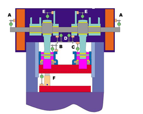
Figure 1 below shows a typical set up for measuring clearances in the main bearings, connection bearings, adjustment mechanism and lower connection pocket/wrist pin area
Safely remove the die from the press. Position the slide to bottom dead center ( 180 degrees of press rotation ). Lockout/tag out power per your companies policies. Reduce the counter balance pressure to zero and bleed off any air from the counter balance system.
Determine the size of jack required to perform the press inspection. As a general rule of thumb, the counterbalance pressure chart used to balance die weight can be used to calculate the size of jack required. For instance, if for each 10 psi change in air pressure, the die weight can be increased by 5,000 pounds and the balance pressure is 40 psi, then the weight of the components and slide is approximately (40psi/10psi) x 5,000 pounds or 20,000 pounds. In this case a jack with a rating >10 ton will raise the slide and components. If the press is a two point press, as shown in Figure 1, the clearances for the right hand and left hand side of the press will be checked separately. In this case a jack >5 ton will suffice.
The jack is placed between the slide face and the bolster. The location of the jack should be close to the center line of the connection. Place an indicator is close proximity of the jack extending from the bolster to the slide face. The sum of the clearances that will be measured should approximately match the indicator reading at the jack
If the jack has a serrated top, protect the bottom of the slide by placing a brass shim between the piston and the slide face.
The contact pressure between the piston of the jack and the slide face should be considered. Limit the contact pressure to 15,000 psi. If necessary use steel spacers of suitable thickness and size between the piston and slide face to limit the pressure and distribute the forces.
Do not use a force that will generate more than 150% of the total weight of the slide and components. If deflection testing was required, larger forces would be necessary and special considerations would be given to assure that no damage to the equipment resulted.
The general condition of the main bearings may be checked by placing indicators at points shown in Figure 1. The intent is to attach the base of the indicator to the structural portion of the crown and measure the vertical movement of the crankshaft when sufficient force is applied by the jack. In the case where access to the main bearing and crankshaft is limited by the press design, an indicator may be placed outside of the interior frame work of the press as shown at point "A". The readings taken at this location will not be exact, but will provide a good approximation that is helpful when comparing the readings taken at point "D".
To begin taking the measurements, lets assume that the clearance on the LH side of the press will be taken first and that the jack and lower indicator are positioned as shown in figure 1. Remove all pressure from the jack to the slide face. Set the lower indicator dial to zero. Place indicators at position "A" and "D" on the LH side of the press. Set dials to zero. Increase the jack pressure until the lower indicator needle stops moving. Record the lower indicator measurement. Record the measurements at points "A" and "D". Release the jack pressure and repeat the test in order to confirm the measurements. They should repeat within 5%. Remove the jack pressure.
Move the upper indicators to points "B" and "E". Set dials to zero. Increase the jack pressure until the lower indicator needle stops moving. Record the lower indicator measurement. Record the measurements at points "B" and "E". Release the jack pressure and repeat the test. Remove the jack pressure.
Remove the indicator at point "E". Move the indicator from point "B" and place the indicator at point "C" on the LH side of the press. The indicator base is attached to the side of the connection and the plunger of the dial indicator is set to the top of the connection screw. The clearance from the wrist pin to the pocket of the connection will be measured.
Increase the jack pressure until the lower indicator needle stops moving. Record the lower indicator measurement. Record the measurements at point "C". Repeat the test to verify. Remove the jack pressure.
Repeat this series of tests on the RH side of the press.
Evaluate the results of the tests.
TAs a rule of thumb, the clearance from journals to bushings is equal to .001" per each inch of journal diameter. If the journal is 5" diameter, then the clearance measured should be .005". The rule of thumb does not hold for journal diameters above 18", high speed presses, or high tonnage presses. In most instances, the allowable clearance can be up to two times the recommended clearance, but is dependant on the part processing requirements, press speed, and counter balance system operation. The press should be operated slightly over counter balanced. The counterbalance system will tend to hold the slide and components "tight together", thus reducing the clearances in the system. Blanking or stripping operations require clearances that are more in the recommended range.
Most important is that the clearances in the RH and LH side of the press are approximately the same! If the clearances are unequal, most likely there is an underlying problem that needs to be addressed in the near future. A bearing could be damaged or the crankshaft cracked. Also, the slide will be subjected to "out of parallel" operation as it operates through its stroke. This can cause undue gib wear and possibly affect forming and blanking operations.
The notes above apply.
The measurements taken at point "B" record the clearances between the lower connection housing and the adjustment assembly. If the adjustment assembly is as shown in figure 1, the total clearance would be a combination of thread clearance and nut to housing clearance. The allowable clearances for threads range from .007" to .020". The allowable clearances for the nuts to housings are from .005" to 015". As stated above, it is most important that the RH and LH clearances are approximately equal.
The measurements taken at point "C" are the clearances between the wrist pin and connection head to pocket. In general these clearances should be minimal ( in the range of .005" - .010" ). Blanking and stripping operations will have a detrimental effect if these clearances are too large. As before, the RH and LH clearances should be approximately equivalent..
Periodic mechanical power press inspection is an essential part of any maintenance program. The above procedure should be repeated at six months intervals. The measurements taken in the previous inspection should be compared with the new, and if necessary, corrective action scheduled.